We're making good progress in our journey into 3D
rendering, but there are some inefficiencies in the approach that we
have used so far that it would be wise to address before we go any
further. These can be addressed by using two new constructs: vertex buffers and index buffers. Let's take a look and see what they can do for us and how they are used.
All the techniques discussed in this section can be seen in the VertexAndIndexBuffers example project. This project adds three cubes to the scene, one of each of the techniques that we are about to explore.
1. Using Vertex Buffers
In all the examples we have used so far, we have called the DrawUserPrimitives
function to render our objects, passing it an array of vertices
containing the object geometry. This works just fine, but is not the
most efficient way of rendering. In order for the graphics hardware to
use the vertex data, all the vertices must be transferred into the
graphics memory.
We can address this performance issue by using a vertex buffer,
which allows the vertex data to reside permanently within the graphics
hardware. The advantage of this approach is that we can switch between
vertex buffers with much less overhead than copying vertex data arrays.
A cube defined using a vertex buffer can be found in the VertexBufferCubeObject
class. There are only a couple of differences between this class and
the cube classes that we have looked at previously. First of all, a new
static class-level variable has been defined of type VertexBuffer and with the name _vertexBuffer.
When the class finds that the vertices have not been initialized, it
creates them as before, but then also uses them to initialize the vertex
buffer, as shown in Listing 1.
Example 1. Creating and initializing a VertexBuffer object
// Have we already built the cube vertex array in a previous instance?
        if (_vertices == null)
        {
            // No, so build them now
            BuildVertices();
            // Create a vertex buffer
_vertexBuffer = new VertexBuffer(game.GraphicsDevice,
                      typeof(VertexPositionColor), _vertices.Length, BufferUsage.WriteOnly);
            _vertexBuffer.SetData(_vertices);
        }
|
The parameters passed to the VertexBuffer constructor are as follows, in this order:
graphicsDevice: the graphics device to which this vertex buffer will be rendered
vertexType: the type of vertex being added to the buffer
vertexCount: the number of vertices to be added to the buffer
usage: special usage flags
Most of these parameters should
be self-explanatory. We know the vertex count because we've already
built an array of vertices, so we can simply read the array size for the
vertexCount parameter. The usage parameter needs a little additional explanation, however. It can be passed as either None or WriteOnly. The first of these options allows the vertex data to be retrieved at a later time (using the VertexBuffer.GetData function), but results in less efficient usage of the buffer in the graphics hardware. The WriteOnly
option optimizes the buffer memory usage, but makes it impossible to
read the vertex data back. It is unusual to need to read the data back
(in this example, we have it in a separate array, anyway), so unless you
need to read the data from the buffer, you should always specify WriteOnly.
This object creation results in an initialized but empty vertex buffer. The vertex data is copied into it by calling the SetData function, passing the vertex array as a parameter.
The buffer is now ready for use, and to render it we need to make some small changes to the object's Draw
function. Prior to drawing we must tell the graphics device which
vertex buffer it should render. Only a single vertex buffer can be set
at any time, so it must be specified before the drawing instruction is
executed. The buffer is set into the device, as shown in Listing 2.
Example 2. Setting a vertex buffer into the graphics device
// Set the active vertex buffer
        effect.GraphicsDevice.SetVertexBuffer(_vertexBuffer);
|
To render with the active vertex buffer, we use a different drawing method. Previously we had been calling DrawUserPrimitives and passing in the vertex array as a parameter. To render using a vertex buffer, we instead call DrawPrimitives.
No vertex data needs to be passed because the vertex buffer from the
graphics device will be used. We just need to tell XNA the primitive
type, the start vertex, and the primitive count, just as we did before.
The code to render the vertex buffer is shown in Listing 3.
Example 3. Drawing the active vertex buffer
// Draw the object
        foreach (EffectPass pass in effect.CurrentTechnique.Passes)
        {
            // Apply the pass
            pass.Apply();
            // Draw the object using the active vertex buffer
            effect.GraphicsDevice.DrawPrimitives(PrimitiveType.TriangleList, 0, 12);
        }
|
Other than these changes, the code and approach is identical to the examples we have already used.
2. Using Indexed Vertices
In order to draw the cube shown
in the previous examples, we have had to provide the same vertex
coordinates to XNA multiple times. As we discussed earlier, a cube has 8
vertices, and yet in our examples we are creating our vertex array with
36 vertices in it, 6 for each face (consisting of 3 vertices for each
of the 2 triangles used to draw the face).
This configuration
of vertices is, of course, quite wasteful in terms of processing
resources because we are calculating the exact same vertex position many
times.
XNA provides an
alternative mechanism for providing the list of vertices that allows the
number of repeated identical coordinates to be reduced. Instead of
creating each vertex independently of the others, we can instead provide
a list of just the unique vertices and then separately tell XNA how to
join them together to make the triangles that it is to render. The list
of vertex numbers that specifies how to join the vertices is simply
stored as an array of numbers.
Consider again the front face of the cube that we saw in Figure 2 in this article.
If we were to specify just the unique vertices, the vertex count would
be reduced from the previous six to four. The four vertices are shown in
Figure 1.
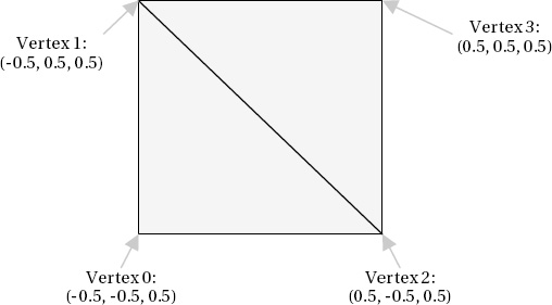
Although this new set of
coordinates allows the vertices to be defined, we no longer have the
information required to join them together to form the rendered
triangles. At this point, the index array makes an entrance. To draw the
front face, we need two triangles, and the vertex indices for each are
as follows:
First triangle: 0, 1, 2
Second triangle: 2, 1, 3
Just as before, the
triangle is formed by specifying its vertices in clockwise order so that
hidden surface culling can hide the triangles when they are facing away
from the viewer.
The only additional
complexity with this approach is that vertices do not only store a
position; they also store colors, texture coordinates, and other
information . Just because two
vertices share the same location, it doesn't necessarily mean that they
are identical.
Each vertex position in our
cube will be part of three different faces (because each corner of the
cube has three squares attached to it), and each face in our example is a
different color. We will therefore need to repeat the vertices for each
face, even though they are in the same position, because they have
different colors.
This still allows us to
reduce the vertex count from the original 36 (6 vertices per face x 6
faces) to a much more efficient 24 (4 vertices per face x 6 faces). The
two redundant vertices within each square face are eliminated, reducing
the vertex count by one-third.
As a result, the code required to
build the vertex array now needs only to specify the unique indexes. The
beginning of the code to generate these vertices, from the IndexedCubeObject class, can be seen in Listing 4.
Example 4. Specifying vertex data for indexed rendering
// Set the vertex positions for a unit size cube.
        i = 0;
        // Front face...
        _vertices[i++].Position = new Vector3(-0.5f, −0.5f, 0.5f);
        _vertices[i++].Position = new Vector3(-0.5f, 0.5f, 0.5f);
        _vertices[i++].Position = new Vector3(0.5f, −0.5f, 0.5f);
        _vertices[i++].Position = new Vector3(0.5f, 0.5f, 0.5f);
|
In order to join the
vertices together, we need to build the array of indices. XNA allows
them to be stored either as an array of short values (permitting a maximum of 32767 vertices), or as an array of int values (with a maximum vertex count exceeding 2 billion), but on Windows Phone only short
values are supported. This vertex limit still allows for very complex
objects and is unlikely to present any practical limitation; it also
saves memory by requiring two bytes per index instead of four.
For rendering a triangle list
as we are, the array needs to be given sets of three indices in order to
identify the three vertices for each triangle. The BuildIndices function sets them all up, and a small section can be seen in Listing 5. The resulting data is stored in the static class-level _indices array.
Example 5. The start of the index array creation
private void BuildIndices()
        {
            int i;

            // Create and initialize the indices
            _indices = new short[36];

            // Set the indices for the cube
            i = 0;
            // Front face...
            _indices[i++] = 0;
            _indices[i++] = 1;
            _indices[i++] = 2;
            _indices[i++] = 2;
            _indices[i++] = 1;
            _indices[i++] = 3;
            // Back face...
            _indices[i++] = 4;
            _indices[i++] = 5;
            _indices[i++] = 6;
            _indices[i++] = 5;
            _indices[i++] = 7;
            _indices[i++] = 6;
|
Note that we store 36 elements
in the array: 6 faces x 2 triangles x 3 vertices = 36 elements in total.
The first triangle is formed from the vertices at positions 0, 1, and
2; and the second triangle from the vertices at positions 2, 1, and
3—exactly as described in Figure 7-16.
The array then continues to form another triangle from vertices 4, 5,
6; and another from vertices 5, 7, 6, and so on for all the triangles in
the cube.
This is clearly quite a lot more
work to set up than simply providing the stand-alone list of vertices,
and in many cases the benefit of this approach will be negligible. In
more complex objects, it can provide a noticeable performance boost,
however. This indexed rendering approach can be taken advantage of
without having to enter pages and pages of index numbers when geometry
is read from external model files and also if you should write code that programmatically generates vertex
coordinates and indices.
To render the cube using the index data, we call the DrawUserIndexedPrimitives function in the Draw function rather than DrawUserPrimitives. In addition to the DrawUserPrimitives
parameters, this call also expects the index array to be provided and
an offset through the index array from which it should start processing
(which we will pass as 0 to specify that it should be processed from the
beginning). The code for this call is shown in Listing 6.
Example 6. Rendering the cube using the index array
// Draw the object
        foreach (EffectPass pass in effect.CurrentTechnique.Passes)
        {
            // Apply the pass
            pass.Apply();
            // Draw the object using the active vertex buffer
            effect.GraphicsDevice.DrawUserIndexedPrimitives(PrimitiveType.TriangleList,
                                           _vertices, 0, _vertices.Length, _indices, 0, 12);
        }
|
This approach results in unnecessary processing of identical vertices to be eliminated in the rendered object.
3. Using Vertex Buffers and Indexing Together
Vertex buffers and
indexing provide optimizations to the way in which our objects are
calculated, and to get the best of both worlds we can use them both at
the same time. When we render an indexed vertex buffer, the vertex
buffer itself is created exactly as we have already seen, but the
indexes are specified in a slightly different way. Instead of storing
them just as an array, we instead place the array data into an IndexBuffer object.
This combined approach can be seen in the VertexAndIndexBufferCubeObject
class. The vertex and index data is created exactly as it was for
indexed rendering, with the reduced number of vertices (24 instead of
36) and the index array joining them together into the finished object.
In the class constructor, both of these arrays are set into buffer
objects, as shown in Listing 7.
Example 7. Creating a vertex buffer and an index buffer
// Have we already built the cube vertex array in a previous instance?
       if (_vertices == null)
       {
           // No, so build them now
           BuildVertices();
           // Create a vertex buffer
           _vertexBuffer = new VertexBuffer(game.GraphicsDevice,
typeof(VertexPositionColor), _vertices.Length, BufferUsage.WriteOnly);
           _vertexBuffer.SetData(_vertices);

           // Create the index array
           BuildIndices();
           // Create an index buffer
           _indexBuffer = new IndexBuffer(game.GraphicsDevice, typeof(short),
                                                    _indices.Length, BufferUsage.WriteOnly);
           _indexBuffer.SetData(_indices);
       }
|
The parameters required when creating the index buffer are as follows:
graphicsDevice: the graphics device to which this index buffer will be rendered
type: the type used for each index array element (short or int)
indexCount: the number of indices to be added to the buffer
usage: special usage flags—None or WriteOnly, just as with the vertex buffer
This object creation sets
up everything that is required to render the indexed vertex buffer. To
actually draw it, we need to tweak the Draw function again.
Just as with the vertex buffer example, we need to provide the vertex buffer to the graphics device using the SetVertexBuffer function. Additionally, we now need to provide the index buffer into the graphics device's Indices property.
With these objects set in place, we render this time by calling the DrawIndexedPrimitive
function. No vertex or index data needs to be passed because the
function reads both of these from the objects set into the graphics
device. Listing 8 shows the complete code to draw the cube using this approach.
Example 8. Drawing indexed vertices from a vertex buffer
public override void Draw(Microsoft.Xna.Framework.GameTime gameTime, Effect effect)
    {
        // Prepare the effect for drawing
        PrepareEffect(effect);

        // Set the active vertex and index buffer
        effect.GraphicsDevice.SetVertexBuffer(_vertexBuffer);
        effect.GraphicsDevice.Indices = _indexBuffer;

        // Draw the object
        foreach (EffectPass pass in effect.CurrentTechnique.Passes)
        {
            // Apply the pass
            pass.Apply();
            // Draw the object using the active vertex buffer
            effect.GraphicsDevice.DrawIndexedPrimitives(PrimitiveType.TriangleList, 0, 0,
                                                                _vertices.Length, 0, 12);
        }
    }
|
This approach provides the
greatest efficiency for rendering in XNA because it reduces the
calculation of redundant vertices and prevents unnecessary copying of
vertex data within the device memory.